8bit Kick Drum Synthesis
Creating a percussive sound using a CPU from 1975
The computers used in my CBM 8032 AV performance, and my own Firebird system do not have a dedicated sound chip. They run with a single MOS 6502 microprocessor, clocked at 1MHz and hooked up to 32kByte of RAM. This neither allows to offload sound generation to specialised hardware such as the famous SID chip of the C-64 computer, nor does it afford sampling. The only solution is synthesis calculated on the CPU itself. This page examines my kick drum algorithm as case study.
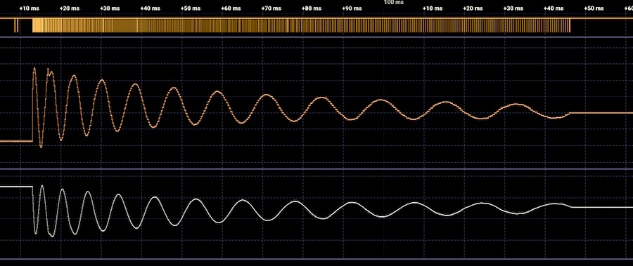
Screenshot above: Waveform of kick #1.The upper waveform is the DAC output, the lower waveform is final result after low pass filtering. The filtered waveform is inverted in the measurement, due to a meanwhile fixed hardware bug.
For each class of sounds like a kick or a snare, hi-hat or bass a dedicated sound generator routine has been developed. In order to run efficiently enough with the limited resources, they have to be crude and clever abstractions, which also gives them their own signature aesthetics. The synthesised sound is sent out to an 8bit digital to analog converter board which has been added to the computer.
For details on the hardware see also here: Firebird and here Inside CBM 8032 AV
The Kick Routine
These are eight variants of a kick sound generated with the kick routine:
The code for the kick is located in memory address $2000. When writing assembler code this has to be specified:
* = $2000 ; start address
The 6502 microprocessor can access data in the first address block ($0000 - $00FF, the so called 'zero page' ) with a dedicated set of commands that allow for faster execution. Most of the addresses are used by the operating system of the CBM 8032, but some are available for user code. We use some of these to store temporary variables:
wait_init = $f4
; initial wait
current_wait = $f5
; wait counter
current = $f0
; variable needed for DSP code, see below
previous = $f1
; variable needed for DSP code, see below
period_count = $f2
; total number of wave periods before stop
pitch_decay_amount = $f3
; we add this to wait_init after each period
init_phase = $f6
; starting point of the wave
The lines above are just definitions, not the code itself. There are a few more global and shared variables in use most notably these two:
NMIFlag = $a2
; raised by the NMI routine when new note did arrive
currentNote = $0ff3
; current note, set by NMI routine
The code starts below. Lines with '; ' are comments, these are not executed, they just help understanding the code. Lines starting with a period like '.resetNMIflag' are 'labels', points in the code that are of significance. They are resolved to physical memory addresses in the actual code and are often used as destination addresses for jumps.
; --- reset NMI re-trigger flag & disable interrupt---
.resetNMIflag
LDA #$00
STA NMIFlag
The presence of a new note is indicated by a non-zero value of the 'NMIFlag'. The NMIFlag is raised by a specific 'interrupt routine' which is triggered when a dedicated physical input pin on the CPU chip, the 'non-maskable interrupt' is getting low. This happens when the sequencer computer is sending a new note to the audio computer. Once we start executing the code for a new sound, this flag needs to be re-set to zero. This is achieved by setting the value of the A register to zero ('LDA, load into Accumulator') and then storing the value of that register into the memory address of the NMIFlag ('STA, store Accumulator to an address).
If we would not do this we would again and again attempt to restart the note and the computer would freeze.
SEI
We also need to turn off the software interrupt (SEI) which is used by the operating system to check the keyboard state and a few more things, triggered by the video chip, 50 times per second. Whilst doing so, this would interrupt the sound generation routine, leading to a nasty 50Hz sound on top of everything else. Since we do not need keyboard access when the sound is running, we can turn this off and making sure the CPU does nothing else than running our code.
Drawing the note ID
.drawBrightID
LDX #$01
JSR DrawID
The computers are facing the audience and the three audio computers are showing the currently playing note number. This happens by calling a subroutine called 'DrawID'. This routine draws the number as a two big hexadecimal letters on screen, to give a visual indication about what goes on. Before calling the drawing routine via JSR ('jump to subroutine') we set the X Register of the CPU to 1.
The 6502 CPU has three internal registers, the Accumulator or A-register, and two 'counting' or 'index' registers X and Y.
This X register is used by the DrawID routine to draw the big number using using filled circles, which from the distance looks brighter than the same number drawn with outlined circles. The outline version is drawn when a note is finished by calling the same subroutine with the value of 0 for X.
Drawing the large note takes around 5ms, during which the computer cannot make any sound. This means there is always a 5ms gap between two sounds.
When we are done drawing the note number, we isolate the lowest three bits of it. This allows us to recall eight variants of the same kick by setting various synthesis parameters.
Grab note parameters
.grabNoteParameters
LDA currentNote
AND #%00000111 ; isolate 8 variations
TAX
On the 6502 CPU we can only do the AND (logical/ boolean AND) on the A register. This is why we load the current note into it, then we strip the higher 5 bits, and then we transfer the result to the X register via TAX (transfer/copy the content of A to X), because X can be used as pointer to memory, with the result stored in the A register.
LDA routine_select_table,x ; which algorithm to select
STA choose_routine+1
The code above stores the value that is represented at the memory location 'routine_select_table' plus an offset that is defined by the value of the X register into the A register.
The value of the A register is then stored in the memory address that follows the 'choose_routine' label. Here we use this to switch between several DSP routines by modifying a jump address.
Set parameters
For the kick routine we need to recall a few more parameters from the preset tables:
LDA hop_size_table,x ; wavetable readout increment
STA hop+3
LDA pitch_decay_table,x ; how fast is pitch going down
STA pitch_decay_amount
LDA period_count_table,x ; how many periods before stop
STA period_count
LDA init_pitch_table,x ; initial pitch
STA wait_init
LDA init_phase_table,x ; initial phase
STA init_phase
My self-made DAC board inside the computer has a switchable lowpass filter. For some of the eight kick sounds this filter is enabled. It is controlled with a bit of code that sets a specific bit in a register on to the DAC board and also displays an icon on the computer screen to provide visual feedback of the filter state.
Since we use this in each sound routine, it is wrapped in a macro ('mSetFilter'). We grab the desired filter state for each kick sound from the 'filter_table'. The result of that indexed addressing of the filter table is in the A register, but the filter macro expects it in the X register. We need to do TAX after getting the value:
Set filter
.setFilter
; --- set filter ---
LDA filter_table,x
TAX
mSetFilter
With an 8bit CPU running at 1MHz we cannot calculate things like normal envelope generators or low pass filters in real time. We are not even close to that, we would need CPU speeds a hundred times faster or more to get this done. No problem for modern CPUs, but impossible with the MOS 6502.
The kick drum algorithm is a great example of what can be done with almost nothing.
What we want to achieve is a cycling waveform that starts with maximum amplitude, and decays over time. We also want the pitch of that waveform to get lower over time. This is how we can do this:
Before start actually playing the note, we fill one block of memory with a pre-calculated sine wave. (A 'block' is 256 bytes). This sine wave has been loaded into the computer together with the sound routines during startup. It has been calculated offline, together with a few other functions that are in use by the various sound routines.
We use the Y register as a pointer both to the sine wave table, which is our source, and also for the TempWaveTable, which is where we copy the wave into. We need to make a copy because we will later modify that wave as part of the sound generation, and require a 'fresh' one each time we start the sound again.
Initialise sine wave table
; --- copy sine table to temporary lookup ---
LDY #$00 ; CPU cycles needed is 2
.copywave
LDA SineWaveTable,y ; CPU cycles needed is 4
STA TempWaveTable,y ; CPU cycles needed is 5
We start with initialising Y to zero (LDY). Then we grab the value from the source table at the index defined by Y and copy it to the temporary wave table, also with the index Y. Then we increment Y, using INY (increment Y register).
INY ; CPU cycles needed is 2
If Y was 255 and we attempt to add 1 one more time, we exceed the possible range of numbers that can be represented with 8bits, and we end with the value of zero for Y. (And the carry bit set, but we can ignore this here). We test the zero condition with BNE (branch if not equal to zero):
BNE copywave ; CPU cycles needed is 3 (2 if no jump)
If the result of INY does not produce zero, we jump back to 'copywave'. Hence this loop runs 256 times, till all values from the source table are copied into the temporary table.
Timing
How long does it take to copy the 256 values? The different operations which the CPU can carry out take a different number of CPU clock cycles, depending on their complexity. The code above shows the CPU cycles needed for each command in the comments: We need two cycles for the first LDA operation. Getting the indexed value needs four cycles, writing it needs five. Incrementing the Y register needs two cycles. The conditional jump needs three cycles when jumping and only two if it does not jump. It jumps back 255 times.
This means we need 2 + 255 * ( 2 + 4 + 5 ) + 2 = 2809 cycles. Since we run at 1MHz this equals 2,809ms. Together with the around 5ms for drawing the big number this adds up to almost 8ms of silence after the note trigger. There is no way around it.
For the kick drum algorithm we need to store the last value that we just sent to the DAC.
This value needs to be initialised to its neutral state when we start a new note. Since we use a linear 8 bit DAC, a value of 0 means full negative amplitude, a value of 255 means full positive and 128 means zero. 128 in decimal values is 80 in hexadecimal notation. We use the Y register again for this job since we do not need it for anything else in that part of the code:
LDY #$80 ; initialise (n_1) for DSP to O.0 Volt
Whilst the MOS 6502 has only three internal registers, we can easily work with that: The Y register has been used to copy the tables, but this job is done, and we can now use the same register to do something completely different. When re-using a register, we only need to make sure we store values that we need later in some external location. In the code which will be executed by the DSP routine the Y register acts as a storage for the previous value set to the DAC. This also implies the Y register cannot be used for anything else anymore as long as this sound generation loop is running.
We now use the X register to represent the phase, which is the momentary position within the temporary wave table. First we set X to the initial phase. It makes an audible difference if the kick starts at a zero crossing or at full volume.
.resetphase
LDX init_phase
All the code above runs one single time when a new note is triggered. At this point we are ready to actually calculate the sound in real time, using some very crude digital signal processing (DSP).
The code which follows below runs as a loop as long as the sound is playing. The time it takes for a loop to complete defines the sampling rate. There is no such thing as a fixed sample rate, we simply try to come up with routines that are fast enough to do the job.
Running the main DSP loop
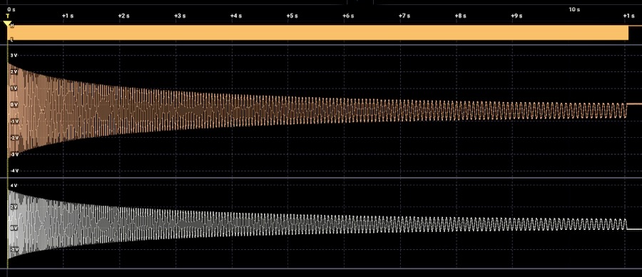 Screenshot above: Waveform of kick #3 with excessive decay.
Run sound generation
; --- MAIN DSP LOOP ---
.mainDSPloop
LDA TempWaveTable,x
We grab the value stored in the TempWaveTable at position X. When we arrive here for the first time after initialisation, X has the 'init phase' value. A will contain the value stored inside the TempWaveTable at location X.
Now we are ready to jump to one of four different routines:
.choose_routine
JMP versionA ; !!! MODIFIED !!!
The four slightly different routines below have different sonic properties. The eight different kick variants each uses one of these routines. We select them by jumping to their start address using the 'JMP' command. The fist byte which follows this command has been modified by the initialisation routine, allowing to only execute one of the four variants.
The main code for the kick is a rough version of a synthesis concept called Karplus-Strong, named after the two researchers who first suggested the concept: During initialisation a temporary lookup table is filled with random values and then during each playback cycle we apply a simple low pass / averaging filter and write the values back.
This causes both a damping in amplitude and a faster decay of higher frequencies.
The 6502 CPU cannot do multiplications, but it can do bit shifting. Shifting a binary representation of a number one bit to the right effectively means dividing it by two (and discarding the fractional part).
Let's see what the algorithm is about by looking at 'version A' of it.
We already copied the value of the temporary table at location X into register A at the beginning of the DSP loop above. Now we divide it by two and store result at a dedicated zero page location 'current' :
; --- Medium Slow Damping n = n * 4/8 + (n-1) * 3/8 + 1/8
.versionA
LSR A ; divide by 2
STA current
We use the Y register to store the previous output, which we did initialise at routine start. Here we recall it by coping its value into the A register for further processing:
TYA ; get previous output
LSR A ; divide previous by 2
LSR A ; divide previous by 2
We divide it by 2 and then again by 2. We store the result in 'previous',
STA previous
'previous now contains the previous output divided by 4. We then divide again by 2 and we add the result of previous:
LSR A ; divide previous by 2
ADC previous ; add previous
This means 'previous' now contains 1/4 + 1/8 = 3/8 of the number in the Y register. We effectively did a multiplication with 0.375 by nothing but bit shifting and addition.
ADC current
'current' contains the current temp wave value divided by two, which we did already at the beginning of the DSP loop. Now we also add this to the A register.
ADC #$20
Finally we add 32 (hex 20) to centre the function around 128. The complete function of this operation is this, where n is the current result and 'n-1' is the result for the last sample we did calculate:
; n = n * 4/8 + (n-1) * 3/8 + 1/8
This is a recursive averaging filter function that puts more weight on the previous value than on the incoming one. Once this or one of the other three damping functions is done, we jump to '.reentry' :
JMP reentry
Timing: From the start of the DSP loop until this point we needed 32 cycles or 0,032mS.
If the jump function that is modified by the preset recall is set to a different value, we might execute one of these three functions instead:
; --- Very Fast Damping n = n *1/4 + (n-1) * 3/4
.versionB
LSR A ; divide by 2
LSR A ; divide by 2
STA current
TYA ; get previous output
LSR A ; divide previous by 2
STA previous
LSR A
ADC previous
ADC current
JMP reentry
; --- Medium Damping n = n * 1/2 + (n_1) *1/2
.versionC
LSR A ; divide by 2
STA current
TYA ; get previous output
LSR A ; divide previous by 2
ADC current
JMP reentry
; --- Slow Damping n = n *3/4 + (n_1) * 1/4
.versionD
LSR A ; divide by 2
STA current
LSR A
ADC current
STA current
TAY
LSR A
LSR A
ADC current
When we arrive here, A contains the result of the damping function calculation for this sample. We transfer it to the Y register, which we use for 'previous sample'.
We also store it at the current position in the TempWaveTable, overwriting the value at the same place which has been set when initialising the function. The resulting value is closer to the 0 Volt value ( 128 / hex 80 ), and when we repeat the function for the same phase a second time we damp it further. This means for each playback cycle of the waveform it gets more damped.
.reentry
STA TempWaveTable,x
We also send the result to the DA converters, because we want to hear it:
STA DAC ; physical location of the DAC.
Now we are ready to declare the current output value as 'previous' value for the next iteration by storing it also in the Y register.
TAY
Now we have been outputting our first sample. To get an audible waveform we need to scan through the complete TempWaveTable a few times.
We do not read out / write back every single entry in the 256 sample long lookup table. This would result in a way too low frequency since the routine above takes a lot of time for each sample. Instead we jump by a power of two, using effectively a 128 or 64 or 32 or 16 samples long table. This brings us further away from an ideal sine wave, but that's part of the unique sound.
Since we use the X register to advance the phase of the waveform, but cannot increment X in any other steps than one, we need to transfer X to A, then add a power of 2 to it, and write it back to X. This is done with CLC (clear carry) followed by ADC ( add with carry ) and the value to add.
This value is modified by the preset recall routine. Note that some presets are actually jumping by steps of 14 or 12, which results in some more complex behaviour. Think about it if you have too much time .... ;-)
.hop
TXA
CLC
ADC #01 ; !!! MODIFIED !!!
TAX
Whilst the damping functions above makes sure the volume decreases over time, another important property of the kick sound still needs to be taken care of: The lowering of the pitch over time.
We use the state of the carry flag to advance a counter each time we finished a complete wave cycle.
Before we perform the addition in the wave table pointer above, we have to clear the carry flag using CLC ( clear carry flag) or the result of the addition (ADC) might be off by one if the carry flag was set by a previous operation.
If the result of the addition in the code above is larger than one block, it folds back to the beginning and afterwards the carry flag is set. This means, if the carry is set, we did one full cycle and can call the pitch decrement function:
If the carry is not set, we jump to '.enterwait'. If it is set, we do the calculations right below. We test the carry flag with the BCC ('branch on carry clear') function:
BCC enterwait ; if we did not reach end of current period we continue
If the cary flag is set, we lower the period counter. The period count value has been set as part of the parameters for each kick sound. We define how many cycles we want the kick to oscillate before we are done with it.
; --- end of period calculations ---
DEC period_count
BEQ noteEnd ; exit if we reach last period
We use DEC to decrement period_count. And then we check if the result is zero (BEQ, branch if equal to zero). If the remaining period_count is zero, we are done and we jump to the noteEnd function.
If the period_count is not zero, we increment the wait time of a wait timer before calculating the next sample:
; --- increment wait timer ----
LDA wait_init
CLC
ADC pitch_decay_amount
STA wait_init
We grab the value stored at 'wait_init'. At note start contains the initial wait time / initial pitch. Then we add the 'pitch_decay_amount', which defines how much the pitch gets lower each cycle. We store the result again in 'wait_init'.
Now we run the actual waiting timer. We load the previously calculated 'wait_init' value into A, then we subtract 1 (SBC, subtract with carry) and check if the result is zero. If it is not zero we jump back to 'wait' and subtract again.
This little loop takes a bit of time, and that time depends on the value of 'wait_init'. The larger the value, the longer it takes to count to zero, and the longer the overall DSP loop takes, and that is the overall sample playback rate. There is of course no interpolation going on anywhere between samples. The steps between the results are just spaced out more in time.
Timing and sample rate calculation now starts to get complex. If we are not at the end of a wave period, getting here took us 22 cycles plus the 32 cycles from the damping function. At the end of each wave period, we have to add 2 more cycles for advancing the period counter and 11 more for incrementing the pitch envelope wait timer. So we end up with either 54 cycles or 65 cycles once per period.
.enterwait
; ---- waiting timer ----
LDA wait_init ; grab wait time
.wait
SBC #01
BNE wait
Timing: The wait timer adds at least 9 cycles, or a maximum of 5 * 255 + 2 cycles.
We exit the loop above when we are done waiting. We could jump back to the beginning of the code and run the next sample. But we somehow need to be able to stop calculating this sound if there was a request from the interrupt routine to play a new note. We do this here:
; --- check if new note arrived and we need to exit ---
.checkNewNote
LDA NMIFlag
BNE new_jump ;if flag > 0 we exit
JMP mainDSPloop
Main DSP Loop Timing
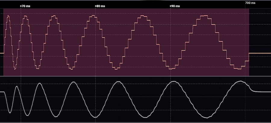 Screenshot above: Waveform of kick #0 with almost no decay and only 6 periods.
Checking the NMI and jumping back takes 9 cycles. This means the sample rate is defined by the sum of all operations from the beginning of the DSP loop till here. In the best case we end up with around 70 cycles, which means a maximum sample rate of 14kHz. This is far from even the cheapest sample based drum computer of the 1980s, but still okay - ish. From the sample rate and from the hop size in the temporary lookup table we can derive the initial pitch of the kick drum. Let's look at preset 1, which has a hop size of 8, and this implies the sine wave is made out of 256/8 = 32 samples. Preset 1 also sets the initial wait time to 6, which implies the DSP loop does not take 70 cycles but 124 samples. So we start at 8kHz sample rate, and 32 samples needed for one period then results in a initial frequency for the kick of 252 Hz. From there we rapidly going down, ending after 13 periods with a wait time of 13*7*9 samples = 819 summing up to a total of almost 900 cycles, or a frequency of 32Hz.
After each sample we check if the NMIFlag has been raised by a new incoming note. If not, we jump back to the beginning of the main DSP loop and calculate the next sample. If yes, we jump to a location called 'jump address', which is modified by the NMI routine and which will contain the start address of the next sound to play.
.new_jump
JMP jumpAddress ; exit to new sound routine
After the end of each wave cycle, we decrement the period counter. If we reached the last period, we are done with our kick sound, and we end up here:
; --- END DSP ---
.noteEnd
; --- draw dim note number ---
LDX #$00
JSR DrawID
; --- exit to draw moving things ---
JMP DrawBars
We now use X for something else again, because we do not need to keep track of the wave table phase anymore. We set it to zero, and jump to the DrawID subroutine. This will draw the current note number in unfilled circles on the screen, hence creating a 'dimmed' version of the active note number, indicating that the routine is not playing anymore.
Then we jump to a routine called 'DrawBars' which creates an animation that runs whilst the computer is not busy with making sound and that routine also checks for the arrival of a new note. If that happens, there will also be a jump to the beginning of a note routine, like this one.
And that's all the code needed to make our kicks.
Right after the physical end of the code in the computer memory, we place the parameters for each of the 8 different kick sounds. The first list contains the jump address that defines which of the four alternative versions of the decay function to use. Since this is referring to a physical memory address, it is important to verify that the correct values are stored in this table, or the routine will jump to the wrong address and crash.
; ---- lookup tables ----
.routine_select_table ; !!!! this changes if code length changes !!!!!!!
EQUB 88,132,132,122, 106,106,106,106
Six other lists contain more variables which need to be set for each kick sound:
.init_pitch_table ; initial value for pitch wait timer
EQUB 3,6,10,12, 2,2,4,2
.hop_size_table ; step size through 1 block sine table
EQUB 14,8,4,4, 4,2,12,4
.pitch_decay_table ; how fast we do lower pitch
EQUB 16,7,6,1 ,5,1,8,5
.period_count_table ; total number of periods
EQUB 6,13,13,240, 10,20,20,10
.init_phase_table
EQUB 0,64,64,1, 64,1,1,64
.filter_table
EQUB 1,1,1,1, 0,0,1,1
And that's it. The CBM 8032 AV Karplus Strong Kick routine plus the parameters for eight presets.
Resources
1. In 1979 Computer sound pioneer Hal Chamberlin wrote one of the most important books about synthesis. In this book he also introduces concepts and source code for digital sound synthesis with early micro processors. I only came across it when I already had developed most of my own sound routines. Well, we all re-invent the wheel. Here it is:
Musical Applications of Microprocessors by Hal Chamberlin.
2. Here is a PDF with the complete assembler and the hex listing of the kick drum routine: 8bitKick.pdf
Dear Reader, I hope you did enjoy this little insight. If you want to see more of that, say a page about how I made my snares or hi-hats, or how I managed to get four decaying voices running afer reading Hal Chamberlin, please let me know: 8bit@roberthenke.com